Difference between revisions of "Historical:SoC 2008 Project OpenGL Preview"
James Legg (talk | contribs) (Intro, started explaning image transformations) |
James Legg (talk | contribs) (blender diagrams for image transformations, more on image transformations) |
||
| Line 5: | Line 5: | ||
===Remapping Vertices=== | ===Remapping Vertices=== | ||
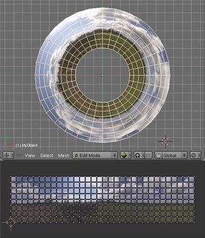
| + | [[Image:Blend_project_mesh.jpg|thumb|Example of using vertices of a mesh to remap an image]] | ||
| + | |||
Taking a point in the input image, we can find where the point is transformed to on the final panorama. Therefore, we can take a uniform grid over an input image, and create a mesh that shows remaps this grid into the output projection. | Taking a point in the input image, we can find where the point is transformed to on the final panorama. Therefore, we can take a uniform grid over an input image, and create a mesh that shows remaps this grid into the output projection. | ||
| − | This method suffers when the input image crosses | + | '''Disadvantages''': |
| + | *This method suffers when the input image crosses over the +/-180° boundary in projections such as equirectangular, as there will be faces connecting one end to the other, and nothing between the edges of those faces and the actual boundary. We must split the mesh so that it each part is continuous, which means some faces will have to be defined off the edge of the panorama. | ||
| + | *The poles of an equirectangular image will cause similar problems. At a pole, the image should cover the whole width of the panorama, but this is only one point in the input image. Vertices in the mesh near the pole are define a face that does not cover the whole row. | ||
| + | *The detail in the faces may not match up well with the area of the panorama. The faces are all of different sizes and some mappings may put the details in parts that can't be seen so easily. | ||
| + | |||
| + | '''Advantages''': | ||
| + | *The mesh resembles the output projection well, and covers up roughly the same area as the correct projection. The edges of the mesh lies along the edges of the image, so we don't need to worry about what happens outside of it. | ||
===Remapping Texture Coordinates=== | ===Remapping Texture Coordinates=== | ||
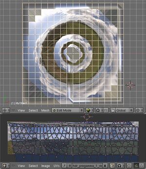
| + | [[Image:Blend_project_UV.jpg|thumb|Example of using the texture coordinates of a mesh to remap an image. The internal repetitions are caused by wrapping the texture in the vertical direction; there should be hole there, but the mesh goes through regardless.]] | ||
Alternatively, given a point on the final panorama, we can calculate what part of an input image belongs there. Therefore, we can take a uniform grid over the panorama, and map the input image across it. | Alternatively, given a point on the final panorama, we can calculate what part of an input image belongs there. Therefore, we can take a uniform grid over the panorama, and map the input image across it. | ||
| − | This | + | '''Disadvantages''': |
| + | *This mapping breaks down at the borders of the input image. The borders of the input image may cross the output mesh at any position, so we need to draw the image with a transparent border. | ||
| + | *We must also calculate the extent of the images in the result so the mesh only covers the minimal area. | ||
| + | *Some faces of the minimal bounding rectangle still don't contain any of the input image at all, processing them would be a waste of time. | ||
| + | |||
| + | '''Advantages''': | ||
| + | *There are no problems at the poles and edges of the panorama. | ||
| + | *The output is of uniform quality throughout, as the faces always have the same density. | ||
===Distortions Comparison=== | ===Distortions Comparison=== | ||
| − | To check that these transformation methods do not distort the image | + | To check that these transformation methods do not distort the image too much, I devised a test. |
| − | Using nona to produce a | + | Using nona to produce a coordinate transformation map from input image coordinates to output image coordinates, and similarly creating a projection that goes the other way, I tried these transformations in Blender. |
Revision as of 20:48, 6 May 2008
The OpenGL Preview project aims to create a fast previewer for Hugin, reducing the time taken to redraw the preview to real time rates. After that, the new previewer can be made more interactive than the current one.
Image Transformations
The new previewer will have to approximate the transformations of the images to fit on low resolution meshes. There are two methods for this:
Remapping Vertices
Taking a point in the input image, we can find where the point is transformed to on the final panorama. Therefore, we can take a uniform grid over an input image, and create a mesh that shows remaps this grid into the output projection.
Disadvantages:
- This method suffers when the input image crosses over the +/-180° boundary in projections such as equirectangular, as there will be faces connecting one end to the other, and nothing between the edges of those faces and the actual boundary. We must split the mesh so that it each part is continuous, which means some faces will have to be defined off the edge of the panorama.
- The poles of an equirectangular image will cause similar problems. At a pole, the image should cover the whole width of the panorama, but this is only one point in the input image. Vertices in the mesh near the pole are define a face that does not cover the whole row.
- The detail in the faces may not match up well with the area of the panorama. The faces are all of different sizes and some mappings may put the details in parts that can't be seen so easily.
Advantages:
- The mesh resembles the output projection well, and covers up roughly the same area as the correct projection. The edges of the mesh lies along the edges of the image, so we don't need to worry about what happens outside of it.
Remapping Texture Coordinates
Alternatively, given a point on the final panorama, we can calculate what part of an input image belongs there. Therefore, we can take a uniform grid over the panorama, and map the input image across it.
Disadvantages:
- This mapping breaks down at the borders of the input image. The borders of the input image may cross the output mesh at any position, so we need to draw the image with a transparent border.
- We must also calculate the extent of the images in the result so the mesh only covers the minimal area.
- Some faces of the minimal bounding rectangle still don't contain any of the input image at all, processing them would be a waste of time.
Advantages:
- There are no problems at the poles and edges of the panorama.
- The output is of uniform quality throughout, as the faces always have the same density.
Distortions Comparison
To check that these transformation methods do not distort the image too much, I devised a test. Using nona to produce a coordinate transformation map from input image coordinates to output image coordinates, and similarly creating a projection that goes the other way, I tried these transformations in Blender.

