Historical:SoC 2008 Project OpenGL Preview
The OpenGL Preview project aims to create a fast previewer for Hugin, reducing the time taken to redraw the preview to real time rates. After that, the new previewer can be made more interactive than the current one. The project is James Legg's Google Summer of Code 2008 project, mentored by Pablo d'Angelo.
Image Transformations
The new previewer will have to approximate the remapping of the images to fit on low resolution meshes. There are two methods for this:
Remapping Vertices
Taking a point in the input image, we can find where the point is transformed to on the final panorama. Therefore, we can take a uniform grid over an input image, and create a mesh that shows remaps this grid into the output projection.
Disadvantages:
- This method suffers when the input image crosses over the +/-180° boundary in projections such as Equirectangular Projection, as there will be faces connecting one end to the other, and nothing between the edges of those faces and the actual boundary. We must split the mesh so that it each part is continuous, which means some faces will have to be defined off the edge of the panorama.
- The poles of an equirectangular image will also cause similar problems. At a pole, the image should cover the whole width of the panorama, but this is only one point in the input image. Vertices in the mesh near the pole are define a face that does not cover the whole row.
- The detail in the faces might not match up well with the area of the panorama. The faces are all of different sizes and some mappings may put the details in parts that can't be seen as easily as the lower resolution parts.
Advantages:
- The mesh resembles the output projection well, and covers up roughly the same area as the correct projection. The edges of the mesh lies along the edges of the image, so we don't need to worry about what happens outside of it.
Remapping Texture Coordinates
Alternatively, given a point on the final panorama, we can calculate what part of an input image belongs there. Therefore, we can take a uniform grid over the panorama, and map the input image across it.
Disadvantages:
- This mapping breaks down at the borders of the input image. The borders of the input image may cross the output mesh at any position, so we need to draw the image with a transparent border.
- We must also calculate the extent of the images in the result so the mesh only covers the minimal area.
- Some faces of the minimal bounding rectangle still don't contain any of the input image at all, processing them would be a waste of time.
Advantages:
- There are no problems at the poles and edges of the panorama.
- The output is of uniform quality throughout, as the faces always have the same density.
Distortions Comparison
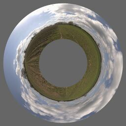
To check that these transformation methods do not distort the image too much, I devised a test. Using Nona to produce a coordinate transformation map from input image coordinates to output image coordinates, and similarly creating a projection that goes the other way, I tried these transformations in Blender.
I projected a cylindrical panorama, 360° wide, and with a pixel resolution 4 times as wide as it is tall, into a fisheye image pointing at the lower pole of the input image, 270° wide, and square.
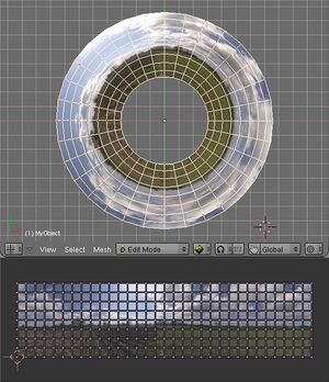
| Vertex mapping Approximate Transformation
This mesh has 32 columns of faces, and 8 rows, across the input image. Since the image is 4 times as wide as it is tall, this means there are 256 faces which cover an equal amount of the input image. |
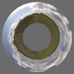
Transformation with Nona
This is the remapping that the other images are approximating. |
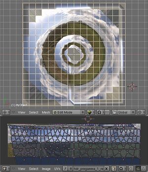
Texture Coordinate mapping Approximate Transformation
This mesh has 16 rows of faces and 16 columns, spread equally over the output panorama, so there are 256 faces which cover an equal amount of the output. Note that at this point I have not attempted to correct the texture coordinates around the boundary of the input image. |
Another test performed was mapping a rectilinear image to the zenith of an equirectangular image.
Modules
As there are many good ideas for the future of a graphically-accelerated Hugin after this project is complete (See the discussion on the mailing list), it is clear that a lot of development can occur using OpenGL and the new preview after I have completed this project. Therefore it is especially important that I provide clean, highly modular and extensible code for future use. Here is a proposal for some modules and interfaces:
- Texture Manager
- The texture manager will be built on top of Hugin's ImageCache, and will perform a similar function but using graphics memory and textures. It will be able to set the active texture to one that represents an image. It should be guaranteed to have a texture for each image when you want to use one, but it won't necessarily give you one that is a good size. It will adjust the size of the textures it is storing so they fill a sensible amount of memory and provide a even level of detail for the images.
- Mesh Manager
- The mesh manager will set up lists of instructions for the graphics system to draw a given image, remapped how it should be in the panorama's output.
- Mesh Transformation Stack
- This will provide the coordinates of points in a mesh. It is a stack so that when only moving the image, we can just recalculate the top of the stack and not have to worry about how distortion parameters are affecting the image. The mesh manager uses the top of this transformation stack. This will also be where coverage tests are performed, so we can identify images under a point.
- Renderer
- This is responsible for drawing the panorama, although it only really compiles a list of render layers and draws them when asked to.
- Render Layers
- Everything the renderer draws would have been put there by a render layer. As the name suggests, they are ordered and can cover each other up. At the end of the project there will obviously be a layer to draw the selected images. Other layers provide indication of image outlines, or perhaps redraw an image in a specific way.
- Image Render Hooks
- When drawing, we may want to do something different for a selection of the images. A render hook can be set up that changes how an image is rendered. It can provide callbacks for before and after drawing, a condition to drop an image from rendering altogether, or a replacement function for drawing it. An example would be to provide different blending modes. We could subtract an image from the ones behind it by dropping it from the images render layer, and then drawing it again in a different render layer, but subtracting it from the layers beneath. Alternatively, if we wanted something drawn in place but semitransparent, we could turn on blending before it is drawn and turn it off afterwards.
- Viewer
- The viewer combines together a renderer and a some basic interface for the tools. It tells the renderer to redraw when the window needs redrawing. Also it stores where in the panorama the user is looking at and how far they are zoomed in. It can convert between a mouse position and a position in the panorama.
- Input Manager
- An input manager gets all keyboard and mouse events the viewer sees and passes them to the correct tool. Tools register events they want. When tools are disabled they should give up their events, which can then be taken by a newly activated tool.
- Tools
- Tools can be enabled or disabled. When switching states they must set up or turn off events in the input manager, render layers, and image render hooks. They get access to the panorama data and viewer data.
- GLPreviewPanel
- This is a replacement PreviewPanel. It holds the viewer and gives it some screen space. It shows controls for the viewer and tools. It will keep an input manager to decide what to do with user input events. Some tools may be mutually exclusive, for example there might be a few that want to handle mouse events. The preview panel should turn off one tool before starting another in this case.
The PreviewFrame will then have an option to switch between the existing PreviewPanel and the new GLPreviewPanel.
Events
Currently there is a PanoramaObserver class, children of this class are notified when the panorama changes. However the viewer is somewhat independent of the panorama, it even makes sense to have multiple viewers of the same panorama. Still, some objects would need to be notified of when the view changes. Therefore we will leave the viewing conditions to the viewer, and provide some more event notifications for when they change. This will be helpful for the texture and mesh managers for instance, since they can change the level of detail as the user zooms on an image. Also any tool that requires this information can also use it.
Additionally, a texture detail change event would be nice, so that when a higher detail texture is ready for use, we can immediately redraw with the higher resolution. This will allow adaptive detail, since we can delay getting the more detailed texture and keep the user interface interactive for a while, and switch when we are ready. Similarly a mesh detail event should be created, this will allow the window to be redrawn after a mesh has been regenerated. We may also need an idle event, so that when we are done processing important things we can consider updating the textures or meshes.
Perhaps it should be possible to delay these events, so that when the preview window is not visible we don't try to update anything. This would mean you can make many minor alterations to the panorama without waiting for any part of the preview to be recalculated, if it was out of sight.
